Description #
OptiGPIO is a General Input/Output board which comes with eight input and eight output. OptiGPIO uses Raspberry Pi4 as a micro controller, and it can be used in any facilities. To connect OptiGPIO with your network, you will need to connect it to Ethernet LAN. Once it is connected, OSC messages will receive the eight inputs, then the output can be opened or closed via OSC message.
Technical Description and Warnings #
- Do not put external voltage onto the inputs. The inputs are internally controlled via the Raspberry Pi4 and the 3.3V of internal voltage.
- The maximum load of each output is written on the relay board. :10A250VAC, 10A 30VDC, 10A125VAC, 10A28VDC.
- The maximum suggested load per output for long time runs is 1000 Watts.
- Relay outputs can be damaged by electrical faults. Make sure each of the loads comes up with a circuit breaker, fuse, overload relay, or any electrical protective devices.
- When using DC supply voltages on the output side, ensure the correct polarity to avoid damage to loads.
- Avoid installing OptiGPIO in the wet area or high humidity.
- Read these operating instructions completely before installing the product.
- Please be cautious that the whole installation process is done by electrical experts to avoid any damage and serious injuries.
Functions #
- The LED indicator will display the status of input and output switches.
- OptiGPIO can be connected to a PC via Ethernet LAN.
- OptiGPIO will use OSC messages to open or close the eight outputs.
- OptiGPIO can be used to control various loads.
First setup #
1. IP address #
Any device connected to a Local Area Network is assigned an IP address. In order to connect to your Raspberry Pi4 from another machine using SSH or VNC, you need to know the Pi’s IP address. there are a number of methods for finding it remotely from another machine on the network. here we recommend the two methods.
1.1 Getting the IP address of a Pi using Your laptop and PC #
The Advanced IP Scanner software for laptop and Pc. It is available for Windows 10.
Laptop,PC and your Raspberry Pi4 have to be on the same network, so connect your phone to the correct wireless network.
When you open the Advanced IP Scanner software, scan button in the upper left-hand corner of the screen. After a few seconds you can click the scan button, you will get a list of all the devices connected to your network. Scroll down to the entry with the manufacturer “Raspberry Pi”. You will see the IP address in the IP column.
1.2 Getting the IP address of a Pi using your smartphone #
The Fing app is a free network scanner for smartphones. It is available for Android and iOS.
Your phone and your Raspberry Pi4 have to be on the same network, so connect your phone to the correct wireless network.
When you open the Fing app, touch the refresh button in the upper right-hand corner of the screen. After a few seconds, you will get a list of all the devices connected to your network. Scroll down to the entry with the manufacturer “Raspberry Pi”. You will see the IP address in the bottom left-hand corner, and the MAC address in the bottom right-hand corner of the entry.
2.Port number #
- number 6000 for receiving OSC messages inputs
- number 7001 for sending OSC messages outputs
How to do the cabling #
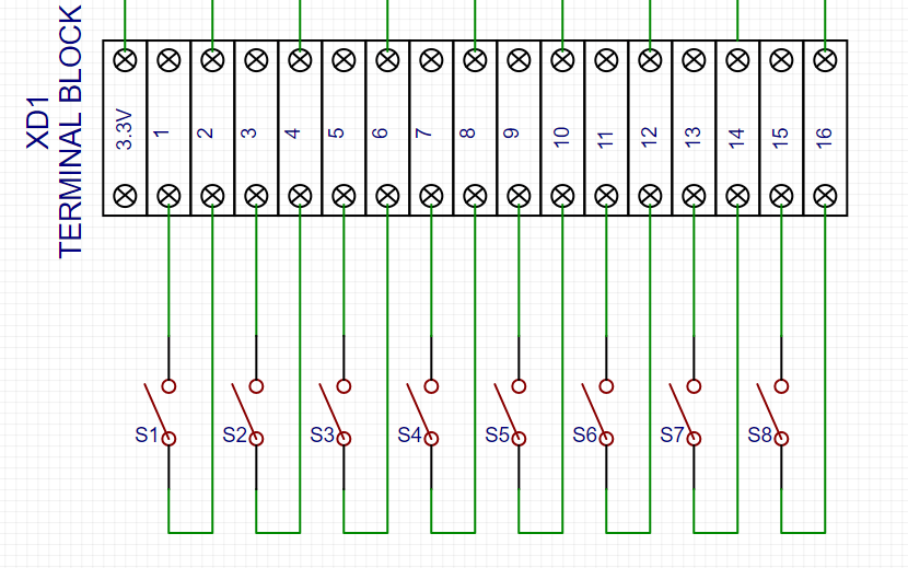
Input
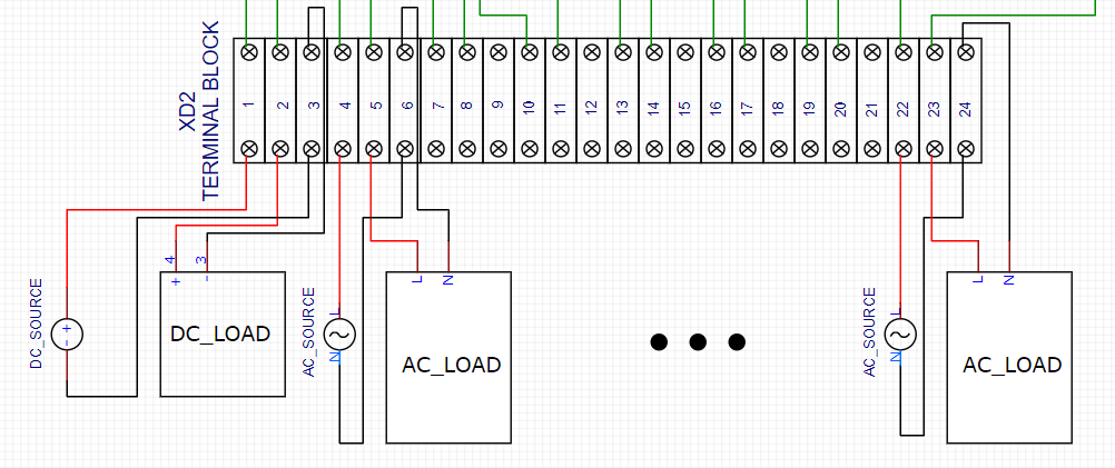
Output
Example:
- Inputs: put 2 terminal cables of each 8 auxiliary switches to input terminal socket.
- Outputs (AC load): put supply line cable to terminal1 on B-side and positive load cable to terminal2 on B-side after that, connect negative load cable to source Neutral cable.
- Outputs (DC load): put positive supply cable to terminal3 on B-side and positive load cable to terminal4 on B-side after that, connect negative load cable to negative supply cable.
- Keep doing this on the sequence until connecting all loads.
How to control via OSC #
- OSC messages inputs -When inputs status receives OSC messages from the eight inputs switch, the status will be shown on OSC input node display (1=Close, 0=Open).
- OSC messages outputs -OSC messages can be used to opened or closed eight outputs and the status will be shown on node display (1=On, 0=Off). Status for Ventus: int5=relay1, int6=relay2 ,…, int12=relay8
Maintenance #
To protect the Raspberry Pi4, the terminal block, and the relay output board against dirt:
- clean the outside of the components only.
- use a suitable vacuum cleaner or voltage-free dry cloth for cleaning depending on the degree of dirt. –
- please be careful when cleaning in order to avoid damage to the wiring and the connectors.
Troubleshooting #
| Trouble | Possible cause | Measures |
| LED indicators do not light When the IP/OP status change | – wiring connection defective – LED indicator defective – incorrect setting port or IP address | – check wiring connection – change the new LED indicator – check port or IP address |
| Raspberry PI4 is not working | – low voltage warning – microSD card defective – CPUdefective | – check power supply and power supply adaptor – please contact the manufacturer: Interactive Asia (IAA) – please contact the manufacturer: Interactive Asia (IAA) |
Installation #
- The OptiGPIO is only suitable for indoor installation. Please avoid wet or high humidity areas.
- Mount the OptiGPIO with 4 screws at an easily accessible wall in the facility.
- When connecting the wiring inside the OptiGPIO, ensure that none of the connections are under excessive strain.
- The connecting adapter for the power supply cable must be connected to 100-240VAC 50/60Hz 0.4-1A.
- The connecting cables for Ethernet LAN communication must be in accordance with the categories CAT5e, CAT6, CAT7, CAT8 with FTP shielding. At the operating locations with increased EMC problems, we recommend using cable types with S/FTP or SF/FTP shielding. Certain details regarding shielding are given in ISO/IEC-11801:2017.
| Color | Signal |
| Blue | TX+ |
| White | TX- |
| Orange | RX+ |
| Yellow | RX- |
Specifications #
| Product name | OptiGPIO 8IO |
| Model | A(8IO) |
| Supply voltage | 100-240V 50/60Hz |
| Supply current | 0.4A |
| Input | 8 switches, no voltage |
| Output | 8 relays |
| LED display input | LED display (Green): light during switches are on, dark during switches are off |
| LED display output | LED display (Red): light during OSC messages are 1, dark during OSC messages are 0 |
| Protective Structure | IP50 |
| Weight | 2.4kg |
| Material | Box case: Acrylonitrile Butadiene Styrene (ABS) |
| Dimensions (W×D×H) | 30x26x15cm |
External dimensions #
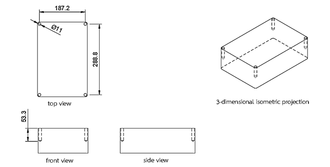
Note: measurement unit in mm


